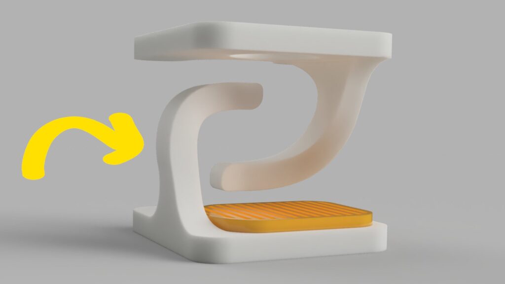
For my second post, I want to share my workflow for creating 3D compound curves in Autodesk Fusions 360, generated by projecting a pair of orthogonal 2D splines. I’ve used this method extensively for designing the sweeping arms of my ongoing Tensegrity Pour Over Coffee Stand project.
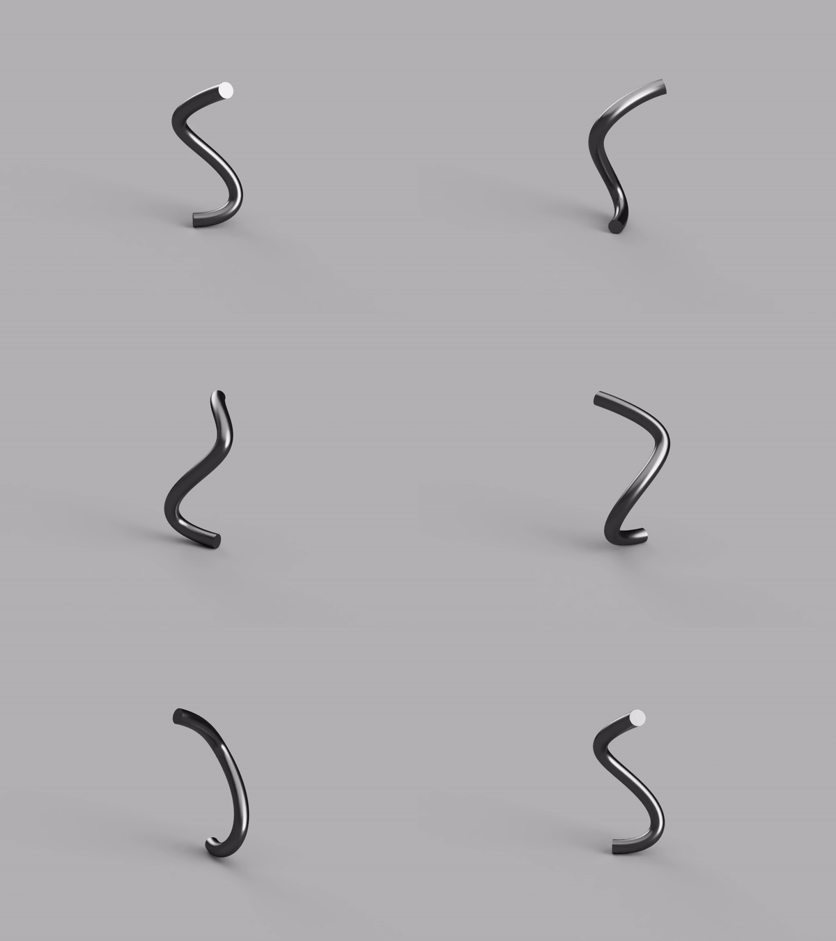
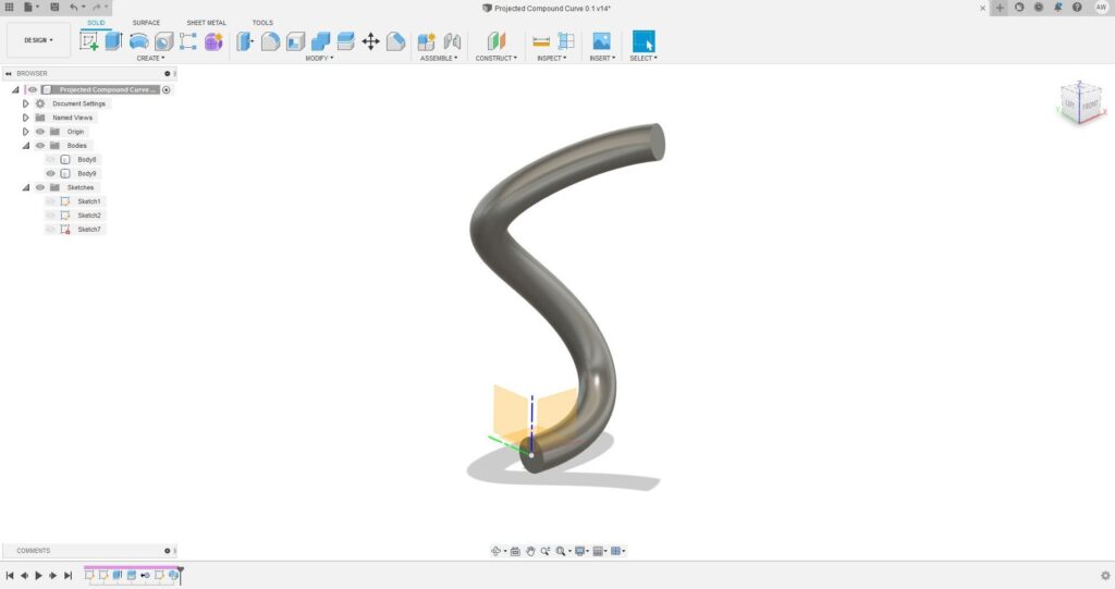
To summarise, we’ll first define two orthogonal curves/splines, then through a series of steps we’ll use these splines to generate a Projected Compound Curve. Pictured bellow is a simple sweep of the example Projected Compound Curve we’ll make in this tutorial.
This workflow is effective but, for lack of a better word, a bit janky. If you’d tackle this differently please let me know, I’d love the chance to build my skills.
Step 1: Define the Front Plane Generating Curve *
To begin, we’ll sketch the first generating curve (or spline) on the Front Plane. For this example we’ll begin the curve at the origin, but in general it doesn’t have to.
The curve should not intersect itself.
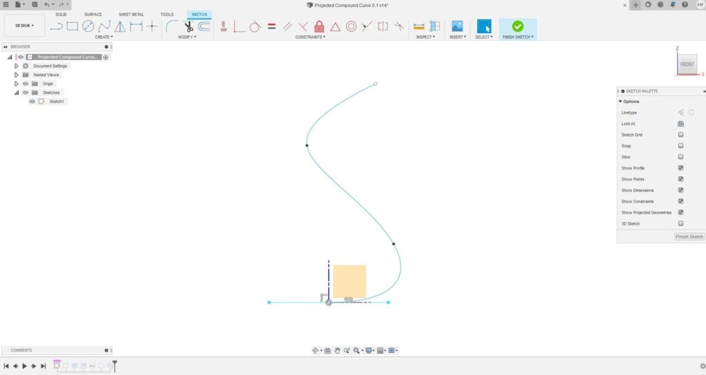
* For this example we’ll create our Generating Curves on the default Front and Left Planes in Fusion 360. In general, any two orthogonal planes can be used.
Step 2: Define the Left Plane Generating Curve
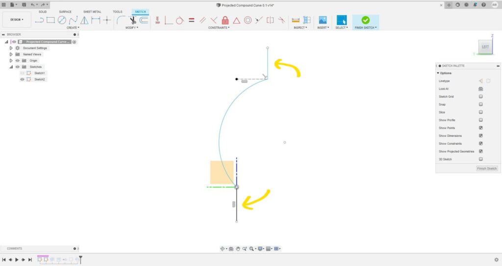
We now sketch a second Generating Curve, but this time on the Left Plane. As before make sure it’s not self-intersecting.
Ensure that in the ‘height’ of this curve matches the Front Plane Curve. By this I mean that the domain of both curves must be the same in the Z axis, as in the example bellow.
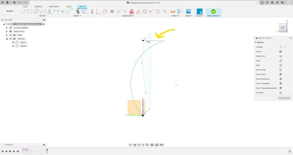
Finally, add short vertical lines to the start and end of this sketch, as shown in the example below. This helps with the later split body step.
Step 3: Prepare the Front Plane Curve for Extrusion
For this step, begin by editing the Front Plane Generating Curve we sketched in Step 1. Add additional lines to the sketch to enclose the Front Plane Curve on one side, as illustrated in the example bellow.
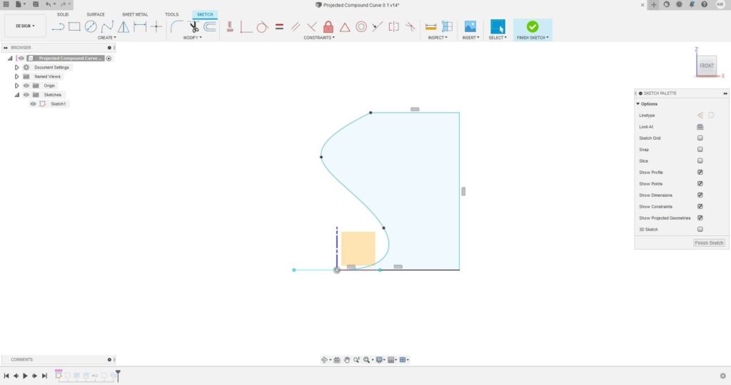
This is probably the least intuitive step of this workflow. What we’re doing is setting up for the extrusion in the next step, which will then be manipulated to create the final Projected Compound Curve.
Step 4: Extrude the Front Plane Sketch
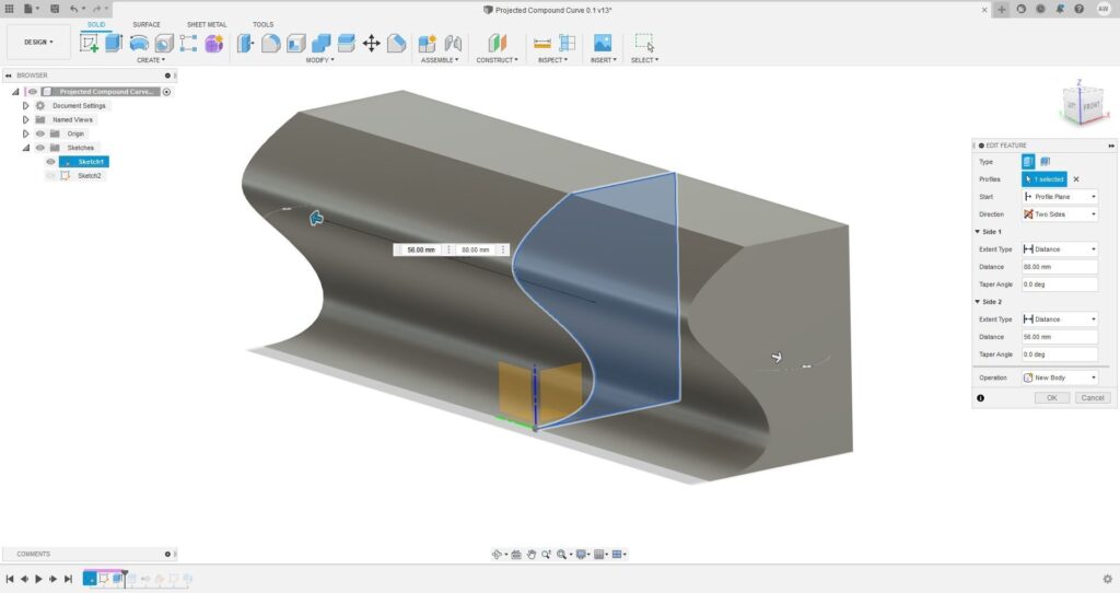
Extrude the modified Front Plane sketch in both directions. Exact distance isn’t important for this, only that the length of the extruded body encompasses the left plane sketch in the Y direction. If you’re unsure, make the extrusion very long.
Step 5: Split Body
Use the ‘Split Body’ tool (under the Modify menu) to split the body (created in the Step 4) with the Left Plane Generating Curve (created in Step 2).
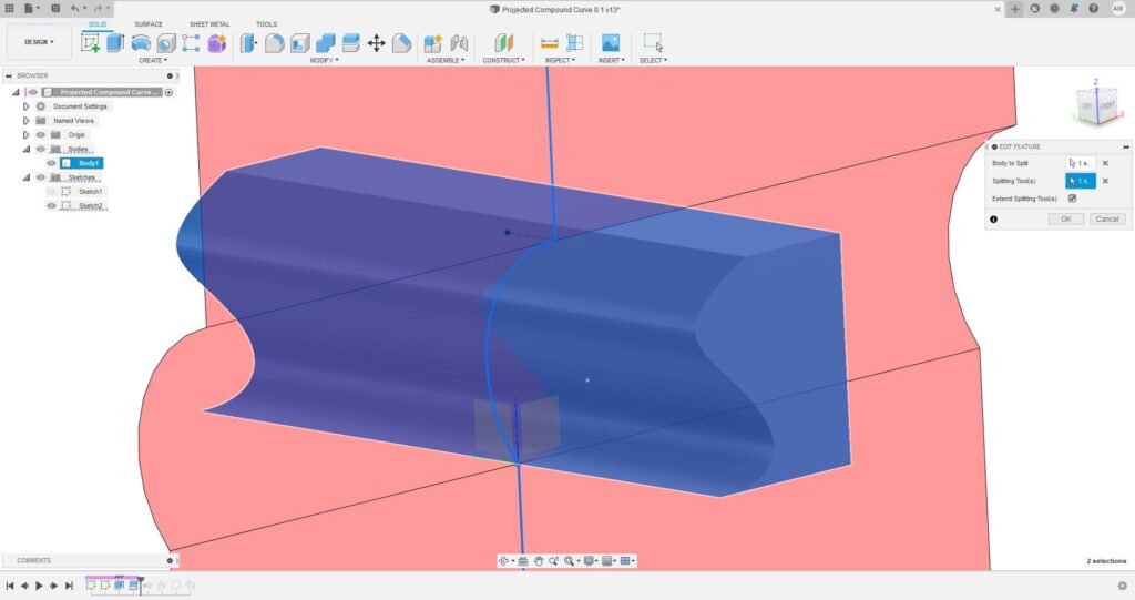
While not strictly necessary, I have found it to be best practice to now remove one of the split bodies (right click on body in the LHS objects list, then select ‘Remove’). Keeping both bodies sometimes causes issues with sweeps.
Step 6: Using the Projected Compound Curve
It might not be immediately obvious, but for the purposes of generating a Projected Compound Curve, we’re actually finished. The leading edge of the split body, where the split occurred, is the Compound Curve we’ve been trying to generate.

The generated Compound Curve can now be used for sweeps or other uses. To complete this example, we’ll use the Projected Compound Curve to create a simple sweep.
Create a new sketch on the Left Plane and draw a circle at the origin. Depending on your particular Compound Curve, it may be better to sketch the circle on the Front Plane, or even define a new plane rotated between the Front and Left Planes, feel free to experiment.
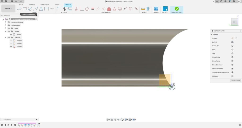
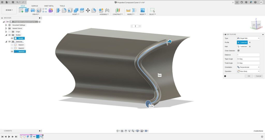
Now create a sweep, setting the circle we just drew as the ‘Profile’ and the Projected Compound Curve as the ‘Path’. If all’s gone right, this should create a simple sweep of our Projected Compound Curve.
Closing Thoughts
Thanks so much for the read, I hope it’s been of some interest or help! I had a blast writing this one, it’s very exciting to be able to share this technique which has been invaluable for some of my recent projects.
Once again, if you have any questions or comments please get in touch, I’d love to hear from you!